Table of Contents
Start Page » Game Development with the Drag[en]gine » Drag[en]gine Integrated Game Development Environment » Rig Editor
IGDE Rig Editor
The rig editor allows to create rig resources for your game (*.derig or else depending on used modules). Rigs are used for Physics with Colliders using Shapes. They are also used for Animators and Animations together with the Animator Editor (*.deanimator).

Rigs can contain these elements:
- Rig shapes (entire rig)
- Bone shapes (bone only)
- Bone constraints (between bones)
Rigs can be used in different configurations depending on what kind of Collider they are used with.
Using Volume Colliders only rig shapes can be used. Rig Colliders or Component Colliders bone shapes and constraints can be used too.
If any bone shapes are present all bones without a shape do not collide and rig shapes are ignored if present.
If no bones have shapes the rig shapes are used for the entire rig.
In paticular this means a rig without any shapes is a Ghost Rig colliding with nothing unless Model Collision is enabled.
The editor window composes of the preview area and the properties panel on the left side.
Preview Window
The preview window shows the preview of the rig. See 3D-View Navigation for how to navigate the view. To see the rig you have to assign a Model Resource and Skin Resource in the view panel. Alternatively you can switch on bones display mode in the Edit menu.
In addition to the regular 3d-view navigation you can activate Physics Simulation by pressing CTRL+Q. With physics simulation activated the rig is set to dynamic collision response and falls to the ground. You can then MOUSE_LEFT dragging on shapes of the rig to move them to check out the physical response. To exit the physics simulation mode press CTRL+Q again. You find simulation mode switch also in the Simulation menu.
Rig

The Root Bone defines the bone to synchronize with the object position and orientation. This is required for rigs used with physical simulation. If missing the object position and orientation is not synchronized to any bones which causes bones to move all over the place potentially far away from the object position. For kinematic or static rigs the root bone is not used.
The CMP parameter defines the Central Mass Point of the entire rig. This is used only for rigs without any bone shapes.
If Model Collision is enabled all shapes (rig and bone ones) are ignored and the Model resource assigned to the collider is used as collision shape. This works only for Component Colliders with a Component resource assigned which has a Model resource assigned.
It is tempting to use model collision as default but it is discouraged. Model collision is usually complex to calculate causing performance drops if used heavily. Try using Shapes whenever possible to get the best performance. If you have to use Convex Decomposition Tools and assign them as Hull Shapes. This is way faster and more stable than model collisions.
If Dynamic is enabled the rig can be used for physical simulation. If this parameter is disabled colliders using this rig will always be animated kinematic even if set to dynamic.
Bone

Shows parameters of the selected bone. To select bones switch to the Bone selection mode in the Edit menu.
The Name is the unique name of the bone. Model, Animation and Animator resources match bones against this name. Hence the rig bone name is the master bone name so to speak.
The Parent is the name of the parent bone. Bone loops are not allowed since bones are organized in a tree like structure. Root bones have no parent. Multiple root bones are possible but for physical simulation only one can be assigned as the rig root bone.
The Position and Rotation are relative to the parent bone or the rig if no parent bone is set.
The CMP is the Central Mass Point of the rig.
The Mass parameter defines the mass in kg of the bone and all the matter connected to it. All bone mass summed together is the rig mass and thus the collider mass.
The best workflow is to set the mass of the bones using a virtual mass like “1 unit” or “5 units”. This allows to specify the mass of the bones relative to other bones. Once you have all bone mass assigned use the Bone → Scale Mass menu command. You can now enter the mass of the entire rig (for example the mass of your actor). The bones mass are then scaled uniformly to make their total sum match the desired rig mass.
If you do not want to figure out individual bone mass for the first step you can use Bone → Mass from Volume menu command. This will calculate bone volumes from the Model resources. You can then specify a scaling factor. The mass assigned to the bone is the calculated volume times this factor.
Activate the Dynamic parameter if this bone has to be simulated using physics. This parameter has no effect if the rig itself is not set dynamic. Dynamic and non-dynamic bones can be combined in the same rig. Be careful using non-dynamic bones parented to dynamic bones. The results might not be what you expect. Using dynamic bones on non-dynamic parents is usually safe to do.
Shape
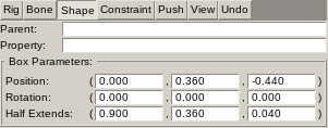
Each bone can have one or more shapes assigned. This panel show parameters of the selected bone shape. To select bone shapes switch to the Shape selection mode in the Edit menu. You can only select visible shapes. Rig shapes are always visible. Bone shapes are only visible if a bone is selected or if Bone → Show All Bone Shapes menu is checked.
The content of the panel depends on the type of the selected shape. These parameters are though present on all shape types.
The Parent is read-only and shows the parent bone of the shape. If this value is empty the shape belongs to the rig itself.
The Property parameter allows to assign a game specific custom property value to the bone shape. This can be used to add per-shape information which can be used during collisions.
Although this field can contain any kind of value it is recommended to store here a game specific Identifier. This way you can use in game scripts a mapping table to store additional information. The Blender Export Script supports assigning shape properties too so you can incorporate them into your modelling workflow.
Constraints

Each bone can have one or more Constraints assigned. This panel show parameters of the selected bone constraint. To select bone constraints switch to the Constraint selection mode in the Edit menu. You can only select visible constraints. Bone constraints are only visible if a bone is selected or if Bone → Show All Bone Constraints menu is checked.
You can also add constraints to rig. These are only for testing purpose for example to simulate a game script adding a run-time constraint to a rig. This can be used for example to test hinging a door to the game world.
Geometry
The Parent is read-only and shows the parent bone of the constraint. If this value is empty the constraint belongs to the rig itself.
The Target parameter set the target bone of the constraint. If this value is empty the constraint is attached to the game world.
The Position and Rotation parameter define the position and orientation of the Constraint Coordinate System. This is the Hinge point so to speak. The values are relative to the Parent Bone Coordinate system. Hence you define the constraint coordinate system relative to the bone you want to attach not the bone it is attached to.
The Offset parameter defines an optional offset applied to the Constraint Coordinate System but from inside the constraint coordinate system.
DOF Linear/Angular X/Y/Z
Defines the linear and angular Degrees of freedom for each axis.
The Range parameter defines the Minimum and Maximum value allowed for the degree of freedom. If the maximum value is equal or less than the minimum value the degree of freedom is locked.
The Friction parameter defines the Friction Forces in Nm. The first value is the Static Friction Force. This is the threshold force before the constraint starts moving. Once moving this force is not more applied. The second value is the Kinematic Friction Force. This force is applied only if the constraint is moving.
The Stiffness parameter defines the Spring Stiffness in Nm. A value of 0 disabled spring behavior. Values larger 0 apply a retraction force towards the original position depending on the displacement of the constraint from the center position.
Damping
Applies Linear, Angular or Sprint damping to the forces acting on the constraint. Damping is a percentage value indicating how much force is destroyed by the damping. A value of 0 applies no damping while a value of 1 destroys all energy literally preventing constraint from moving at all.
Rope
If Use Rope Physics is enabled the physics module treats the constraint as a Rope Constraint. Physics modules tend to use a different simulation algorithm for ropes to improve the stability.
Breaking
The Breaking parameter defines the amount of impulse (Ns) that has to apply on a constraint before it breaks. A broken constraint is disabled and can be enabled again. If the value is zero the constraint never breaks.
Push

You can add Pushes to simulate impulses applied to a rig at the beginning of Simulation Mode. This allows to examine how a rig (typically a rag-doll type rig) behaves to an impact event during the game. Useful in this situation is using Slowmotion from the View Panel. Pushes are visible in the view as an arrow pointing at the position to applied the push to (arrow head) with the arrow direction indicating the direction of the push.
The Type parameter indicates what kind of push to apply. Supported are Simple Push and Explosion. Simple push applies a single impulse to the rig at the start of a simulation run. Explosion push applies a bunch of impulse at the same time spread along a cone.
The Position and Orientation define the position where the push is applied and the direction of the push.
The Impulse defines the amount of impulse in Ns to apply. If explosion type is used the impulse is evenly distributed across all applied impulses.
The Ray Count defines the count of rays to use for explosion type push.
The Cone Angle defines the angle in degrees of the cone to use for explosion type push. Rays are evenly distributed across the cone.
View
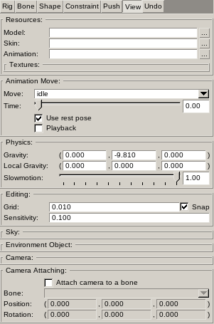
The Resources panel defines the Model, Skin and Animation resource to use to preview the rig. Without a model no Simulation Mode is possible.
The Animation Move panel defines the animation move to play. Requires an Animation resource to be assigned to work. The rest pose is shown if the Use rest pose parameter is ticked. If Playback is ticked the animation move is played in a loop otherwise the desired animation frame (in seconds) is shown.
The Physics panel defines the World Gravity and Local Gravity to use. World gravity applies to the bones in the rig while local gravity applies to the preview component itself. The Slowmotion parameters defines the update speed of the simulation and allows to examine physical behavior in closer detail to spot problems.
The Sky panel defines the Sky resource to use in the preview view.
The Environment Object panel defines the Object Class to use as environment the rig is previewed in.
The Camera panel shows the parameters of the camera in the preview view. The values can be manually edited.
The Camera Attaching panel allows to attach the preview view camera to bones in the rig.
